Comparison of Integrators Using a Simple Pendulum in DynaMechs
Revision 1.0 2022-10-03
As we continue to look at the DynaMechs library, we decided to perform a quick investigation of the different integrators that it offers. DynaMechs has implementations of explicit Euler, Runge-Kutta (fourth order), and an adaptive stepsize Runge-Kutta. DynaMechs makes it easy to add more integrators, so we decided to add semi-implicit Euler, and the α-parameterized Runge-Kutta second order integrators. We then performed experiments on a simple pendulum setup in DynaMechs to see how the integrators compared; for example, the received wisdom is that explicit Euler gains energy, semi-implicit Euler conserves energy, and Runge-Kutta integrators tend to lose energy.
Pendulum Setup
To make the calculations simpler, we tried to make the DynaMechs setup as close to a simple gravity pendulum as possible. A 1mm diameter sphere of uniform density and mass 1kg was placed 1m along the X axis of a DynaMechs RevoluteJoint, the joint type chosen to constrain the sphere to move within a plane. The pendulum motion was started with an initial angle to the vertical of 0.1rad. Joint friction was set to zero and in the absence of any other resistances it was expected that the pendulum would oscillate between ±0.1 radians indefinitely.
Before simulation, the first few terms of the power series correction to the linear equation were used to obtain a prediction as to the anticipated period of the pendulum:- $$\displaystyle T=2\pi {\sqrt {\frac {L}{g}}}\left(1+{\frac {1}{16}}\theta _{0}^{2}+{\frac {11}{3072}}\theta _{0}^{4}+{\frac {173}{737280}}\theta _{0}^{6}+{\frac {22931}{1321205760}}\theta _{0}^{8}+{\frac {1319183}{951268147200}}\theta _{0}^{10} \right)$$
Which for \(L=1.0m\), \(g=9.80665ms^{-2}\) and \(\theta _{0}=0.1rad\) results in \(T=2.00766s\) (this is of course an approximation as more terms can be added to the series).
Experiments
Explicit Euler vs. Semi-Implicit Euler
The first simulation run was done with a lead-in period of 0s and a timestep of 0.00001s, with the aim of verifying the estimated period of the pendulum as calculated just above. All the integrators began simulation with the angle of the pendulum \(\theta _{0}=0.1rad\) at \(t=0s\). Looking through the dataset, we extracted the time indices when the pendulum was next at that angle (or closest to it). The outcome was that the explicit Euler was early by some margin in comparison to the other integrators, which themselves aligned very well with the estimated period:-
| Integrator | Simulated pendulum period (s) |
|---|---|
| Explicit Euler | 2.00320 |
| Semi-Implicit Euler | 2.00767 |
| RK2 (Heun) | 2.00767 |
| RK2 (Midpoint) | 2.00766 |
| RK2 (Ralston) | 2.00767 |
| RK4 | 2.00767 |
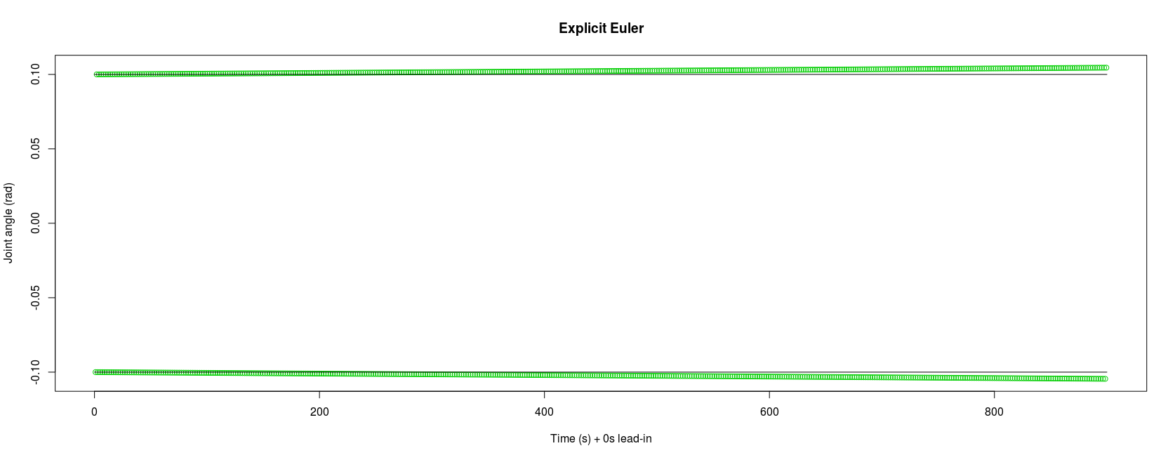
To investigate explicit Euler deeper, we loaded the dataset into R to obtain a graph of the oscillations over the first 15 minutes (here the green circles show the inflection points of the pendulum movement and the horizontal lines show ±0.1 radians). It can clearly be seen that using the explicit Euler integrator the pendulum oscillations immediately begin diverging from the expected limits and the error continued to grow.

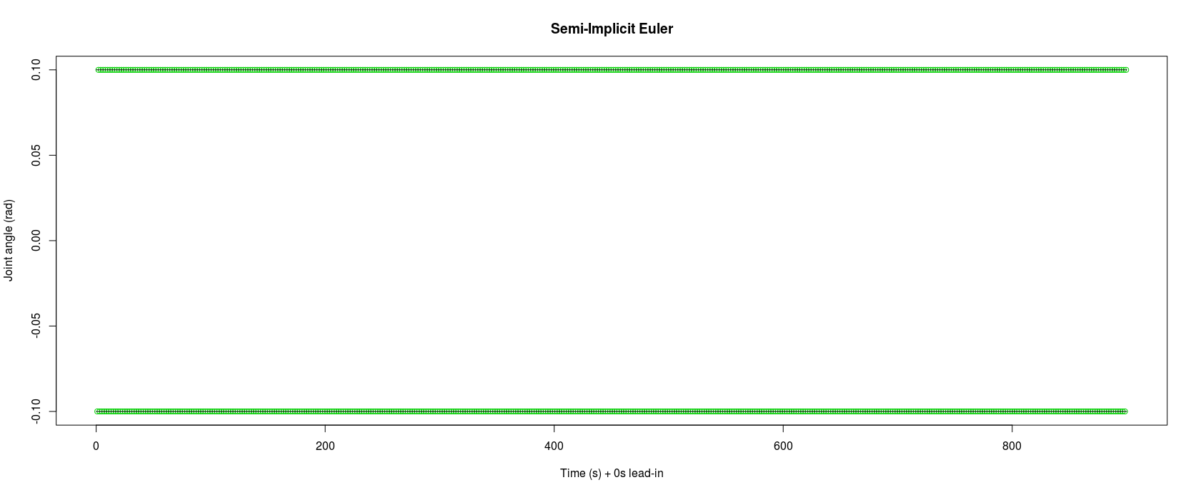
In comparison the semi-implicit Euler manages to maintain the expected ±0.1 radians:-

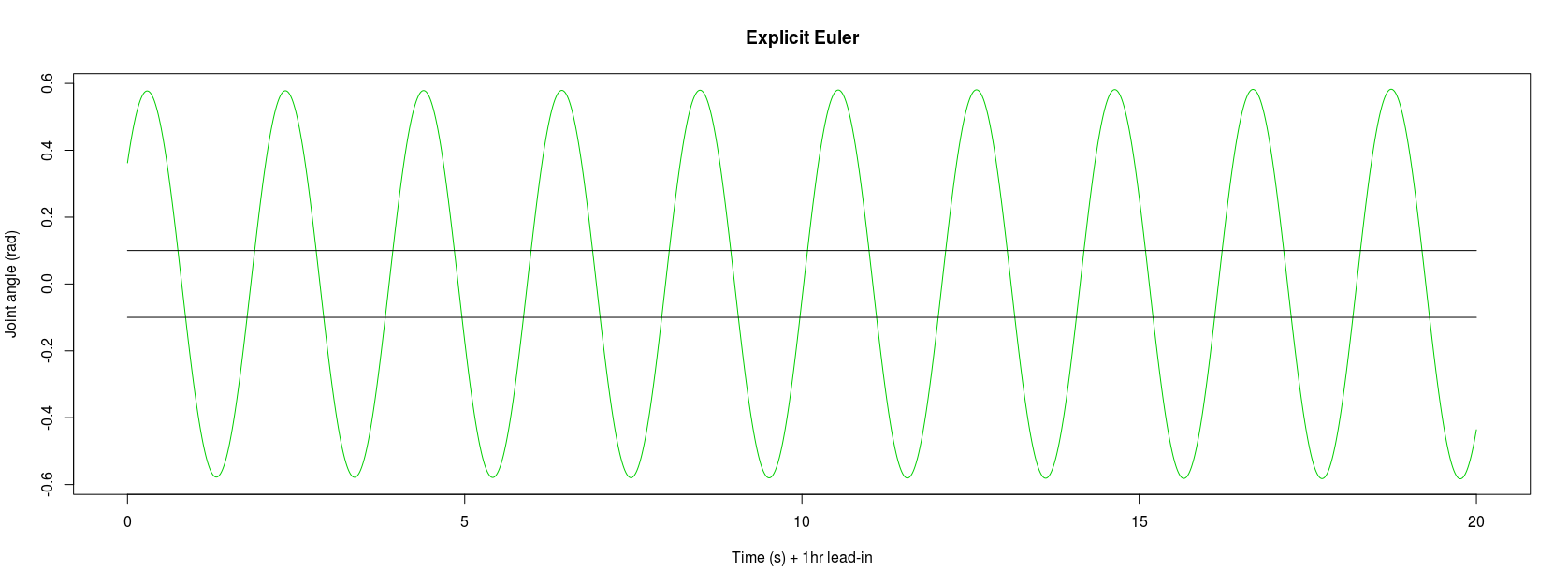
To continue the experiment, we reduced the simulation timestep to 0.0001s and then observed the pendulum motion for each of the integrators after simulating 1 hour, 1 day, and finally 1 month; the idea being, to allow any errors to accumulate. Looking at the explicit Euler again after only 1 hour of simulated pendulum swinging and it had diverged from any form of reality, now reaching ±0.6 radians:-

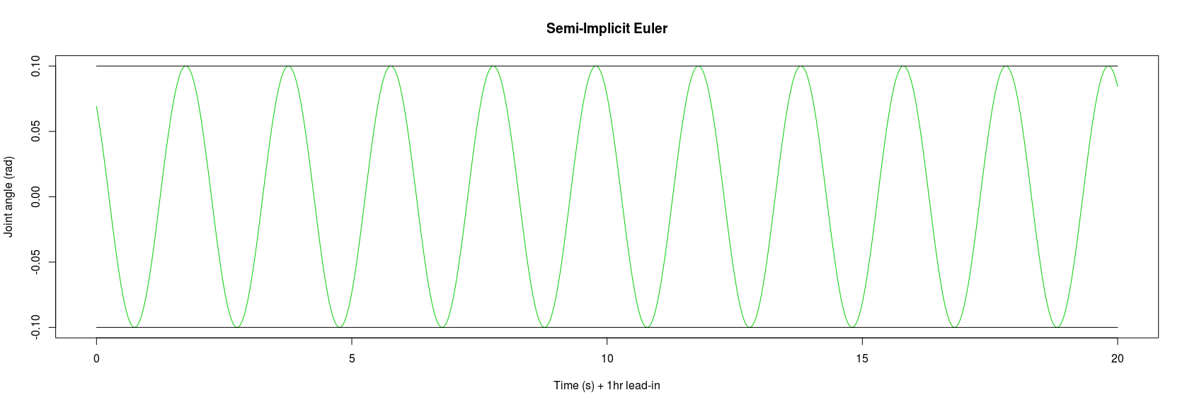
After the same lead-in time the semi-implicit Euler continued to stay constrained to ±0.1 radians:-

So it would seem that the reputations of explicit Euler to gain energy, and semi-implicit Euler to conserve energy are deserved.
Runge-Kutta
The Runge-Kutta integrators performed far better than the explicit Euler. Observing the pendulum motion after thirty days of continuous swinging the RK4 integrator still showed a pendulum period of 2.0077s, and an arc sweep of 0.2 radians (accurate to at least 9 decimal places, i.e. the pendulum was swinging between 0.100000000 rad and -0.100000000 rad). However, in an unexpected result, the various RK2 integrators we were testing (Heun, mid-point, and Ralston) all gained energy very slightly, the arc of the pendulum having very gradually increased over time. This increase was so small as to be practically negligable, however it was present. The semi-implicit Euler also seemed to gain energy, but to an even tinier degree, to the point where it might not even be a real observation:-
| Integrator | Pendulum arc length at start (rad) | Pendulum arc length after thirty days (rad) |
|---|---|---|
| Semi-Implicit Euler | 0.200000000 | 0.200000001 |
| RK2 (Heun) | 0.200000001 | 0.200000518 |
| RK2 (Midpoint) | 0.200000008 | 0.200000524 |
| RK2 (Ralston) | 0.200000005 | 0.200000519 |
| RK4 | 0.200000000 | 0.200000000 |
Speed of Integrators
We would expect the calculation of the dynamics to be the major cost in an integrator, and looking at the relative durations for simulating one month of pendulum swings bears that out. The explicit and semi-implicit Euler integrators, which call the dynamics once, require half the duration of the RK2 integrators, which call the dynamics twice per timestep. The RK2 integrators are in turn half the duration of the RK4, which calls the dynamics four times per timestep. There are differences within classes of integrator, but as our computer was running other processes during the experiments it would be unreasonable to expect the durations to be practically identical.
| Integrator | Time take to simulate 1 month (2,592,020s) of pendulum swings |
|---|---|
| Explicit Euler | 490.189s (8m 10.2s) |
| Semi-Implicit Euler | 468.467s (7m 48.5s) |
| RK2 (Heun) | 925.802s (15m 25.8s) |
| RK2 (Midpoint) | 929.525s (15m 29.5s) |
| RK2 (Ralston) | 929.627s (15m 29.6s) |
| RK4 | 1862.450s (31m 2.5s) |
Conclusions
This was just a quick look at some integrators available with the DynaMechs library, with experiments on the simplest possible mechanical setup, a simple gravity pendulum. We were expecting the explicit Euler to not perform particularly well, but the rate at which it deteriorated was a surprise — even using a very small time step it would seem to be a poor choice. The semi-implicit Euler performs far better for that kind of oscillatory motion, without requiring more calls to the dynamics.
Of course, the choice of integrator very much depends on the nature of the system and the final deliverable. For the kind of simple linkage systems and short timescales we are experimenting with (robot arms etc.) most integrators are probably fine. The idea that RK4 loses energy is probably from applications like orbital dynamics where planetary systems are simulated over very long timescales and to very high degrees of precision. The observation that the RK2 integrators might be gaining energy is a surprise and might require a further look when we have the time.